 This article will discuss the main components of the truss system and how to attach them to the Mauerlat and run.
Before considering the individual nodes of the truss structures, it is worth clarifying which factors determine the reliability of the rafter system:
- The right choice of type truss system;
- The strength of the joints in the nodes of the rafter system;
- Correct calculation of planned loads on the roof;
- Competent choice of roofing material;
- Skill and qualification of workers.
It follows that the equipment of the truss system requires the careful implementation of the required calculations and the project, the competent preparation of the plan and the availability of the required knowledge and skills from the workers who perform its installation.
Do-it-yourself rafter construction may not be the best choice, as it may reduce the reliability of the resulting structure.
The main components of the rafter system
The truss system - nodes, type and design - is determined taking into account the following factors:
- The proposed shape of the roof;
- The dimensions of the space to be covered;
- The presence and location of internal supports or load-bearing walls.
As an example, consider the truss schemes of standard gable roofs, where load-bearing walls are located at different distances.
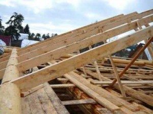
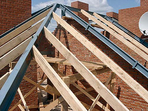
If the length of the overlapped span does not exceed six meters, it is recommended to build a system of layered rafters, when the rafters from timber, logs or boards rest on a support beam (Mauerlat) located along the perimeter of the building.
This allows you to significantly reduce the consumption of materials used for the construction of the rafter system.
Useful: if the distance between two load-bearing walls is up to 8 m, opposite rafters made of logs, beams or boards should be connected with a crossbar.
Another option for using the rafter system is to use intermediate posts that rest on posts or walls located inside.
Such a system is able to cover a 12-meter distance between the walls in the case of installing one additional support, or 16 meters - when installing two supports.
If the distance between the bearing walls is up to 12 meters, and there are no internal supports, it is recommended to choose a system hanging rafterswhen the fulcrum of the rafters is on a solid (or, in rare cases, on a composite) puff, which, in turn, is located on the Mauerlat.
The assembly of rafters from logs, beams or boards in this case will include the following main components:
- Skate knot;
- Rafter support unit;
- Knot "struts-rack-beam";
- Knot "rack-strut-rafter".
Depending on whether there are additional elements in the construction of the rafters, such as crossbars, tightening, etc., other nodes can also be used.
After developing the overall design and the main components, a plan for the rafter system, which is part of the project, should be drawn up.
Consider, as an example, the main support nodes for a layered truss system.
Support nodes of layered rafters on the run and Mauerlat

Distinguish between expansion and non-expansion layered truss systems.
On how correctly the rafter knots and the connection of the legs of the rafters are chosen, such moments as the bursting of the walls by the rafters, the need to provide for the interception of the thrust, etc. depend.
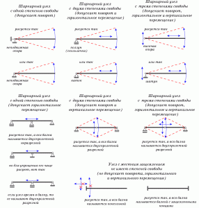
When compiling design schemes, circles are used to designate hinged joints in structural units.
Hinges with the help of paws are connected to conditional supports, which allow visualizing the degree of freedom of any node:
- Two hinge legs embedded in the support assume the immobility of the assembly, while allowing rotation of the beam in the hinge. Such a node has one degree of freedom - rotation.
- If the hinge legs are mounted on a slider or a sliding support, this node has two degrees of freedom - in addition to the rotation of the beam, there is also a horizontal displacement.
- In the case of providing three degrees of freedom of the node (horizontal and vertical displacement, as well as rotation), the node is indicated on the diagram simply by a circle.Such a node can be cut into a bar that represents a beam.
In the case of cutting a node into a beam, it is called a split one. Beams, which are located on the left and right of the hinge, can be conditionally considered as separate elements.
If the circle denoting the hinge is drawn below the beam, such a beam lying on the hinge is called continuous.
When a hinge, which has three degrees of freedom, is cut into a beam, most often it turns it into an instantly changeable system, such a design is rather unstable.
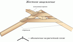
There are also nodes that have a zero degree of freedom, while the end of the beam is rigidly clamped, prohibiting any of its displacement both horizontally and vertically.
It is important to take into account that the concepts of horizontal displacement and rotation do not imply, for example, arbitrary horizontal movement of a slider - a node with two degrees of freedom.
This node is fixed quite reliably, but allows the end of the beam to move under the influence of loads, changes in temperature and humidity, and in the node itself, excessive internal stresses do not occur.
This node does not transfer the thrust, and in the case of beam bending, the rotation is performed only within the limits that comply with the regulations. This node can “crawl” only if the current loads exceed the maximum allowable.

The term "hinge" should also not be taken literally. Although both bolts and a specially designed real hinge can be used to connect the ends of the beams, in most cases, a hinge is understood as a simple connection with nails.
For example, a board nailed to the wall at one end with several nails can be turned through a small angle by pressing on the other end. In this case, the fastening with nails acts as a hinge.
But an increase in the number of nails, designed for such a load that does not allow bending (cutting), makes it impossible to turn and the board becomes a beam with a pinched end. Exceeding the calculated load again turns the mount into a hinge.
In this regard, it is necessary to calculate in advance under what load it is planned to operate the system.
A situation where the current load exceeds that calculated in the project can lead not only to a change in the operating mode of various nodes, but also to partial or even complete destruction of the truss structure.
Schematic representations of some options for junction nodes of layered rafters are shown in the figure. Depending on the specific roof project, the joints of the rafters may differ from those shown in the figure.
The most important is the design in the nodes of two degrees of freedom:
- The turn resulting from the bending of the rafters;
- Shift directed horizontally.
In nodes with one degree of freedom, it is important to design the rotation of the rafter.

Most often, horizontal cuts are provided to shift the upper or lower part of the rafters, and to limit the shift, the rafters abut either against each other or against the element with which they are joined (run or Mauerlat).
Consider an example explaining the principle of fastening the rafters. Let us mentally attach a standard ladder to the wall, consisting of two poles (strings) and transverse sticks - steps.
Fill the wall and floor with oil to minimize friction.
Now the ladder will fall when you try to climb it, because it has two degrees of freedom both at the top and bottom points of support:
- Rotation and horizontal displacement at the lower fulcrum;
- Rotation and vertical shift - at the top.
In order to give it stability, allowing it to withstand the load in the form of human weight, it is enough to deprive it of only one degree of freedom out of four: horizontal displacement at the bottom or vertical displacement at the top.
It is enough to fix the top or bottom of this ladder, resulting in a stable and stable system.
You can continue to mentally experiment with different versions of the stairs, for example, changing its length or adding horizontal cuts to the bowstrings and analyzing its stability.
This helps to better understand the principle of operation of the layered truss system, when different flooring on the rafters, as well as various support methods, can be taken into account.
In this case, it is not required to imagine various vectors and degrees of freedom in your head, it is enough to imagine - the ladder will remain standing or roll down to the floor under the influence of the load.
That's all I wanted to talk about the various nodes of the rafter system. It should be remembered that the correctness of their calculation and the quality of performance directly affect the ability of the roof to withstand various loads.
Therefore, in order to avoid damage or destruction of the roof, the design and construction of the rafter system must be carried out by qualified specialists.
Did the article help you?
