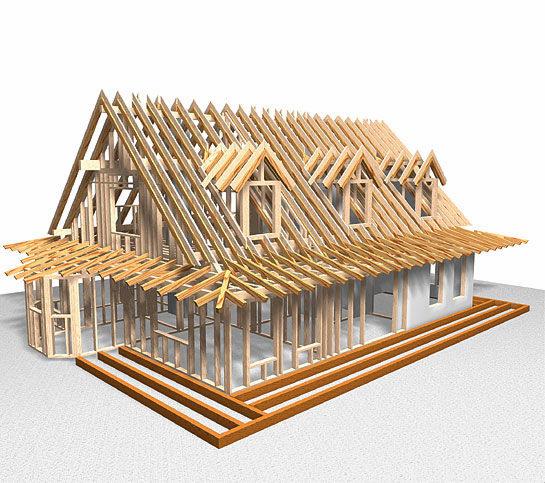
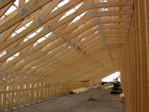
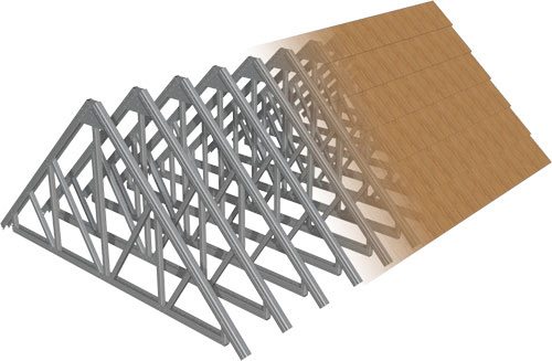
 The weather conditions of our country are fickle, so the rafter system of a house under construction must have sufficiently high reliability and durability. This article describes how to calculate the rafters and truss system, various loads on them and provides an example of such a calculation.
Regardless of the chosen shape of the future roof, its rafter system must be strong enough, for which it is necessary, first of all, to correctly and correctly calculate the truss system.
The primary task of the designer and architect is not to design the appearance of the building, but to carry out a qualitative calculation of the strength of the planned house, including its rafter system.
The calculation of the rafter system includes a number of different parameters, which include:
- weight roofing materialsused to cover the roof, for example - soft roof, ondulin, natural tiles, etc .;
- weight of materials used for interior decoration;
- the weight of the structure of the rafter system itself;
- calculation of beams and rafters;
- external weather effects on the roof and others.
In the process of calculating the truss system, it is imperative to calculate the following positions:
- Calculation of the section of the rafters;
- Rafter pitch, i.e. the distance between them;
- Spans of the rafter system;
- Designing a truss truss and choosing which rafter attachment scheme - layered or hanging - will be used during construction;
- Analysis of the bearing capabilities of the foundation and supports;
- Calculation of such additional elements as puffs that connect the structure of the rafters, preventing it from “driving around” and braces that allow “unloading” the rafters.
When using a typical project, there is no need to think about how to calculate the truss system, since all calculations have already been completed. In the case of construction according to an individual project, all necessary calculations should be performed in advance.
Study do-it-yourself roofing and calculations should be a specialist with sufficient qualifications and having the necessary knowledge and skills.
Requirements for structural elements of rafters

For the manufacture of structural elements of the rafters, coniferous wood is used, the moisture content of which should not exceed 20%.
modern roofing wood material pre-treated with special protective preparations. Parameters such as the thickness of the rafters are selected in accordance with the calculations discussed below.
Loads that affect the design of the rafters and in connection with which it may be necessary to strengthen the truss system, according to the duration of the impact, are divided into two categories: temporary and permanent:
- Permanent loads include loads created by the own weight of the rafter structure, the weight of materials for roofing, battens, thermal insulation and materials used in finishing the ceiling. They are directly affected by the size of the rafters;
- Live loads can also be divided into short-term, long-term and special. Short-term loads include the weight of roofing workers and the weight of the tools and equipment they use. In addition, short-term loads include wind and snow loads on the roof. Special loads include rather infrequent actions such as earthquakes.
To calculate the truss system using the limit states of these load groups, it is necessary to take into account their most unfavorable combination.
Snow load calculation

The most complete calculated value of the snow cover load is calculated using the formula:
S=Sg*µ
- where Sg is the calculated value of the mass of snow cover per 1 m taken from the table2 horizontal earth's surface;
- µ is a coefficient that determines the transition from the weight of the snow cover on the ground to the snow load on the roofing.
The value of the coefficient µ is selected depending on the angle of slope of the roof slopes:
µ=1 if the slope angles of the roof slope do not exceed 25°.
µ=0.7 in the case when the slope angles of the slopes are in the range of 25-60°.
Important: if the slope of the roof slope exceeds 60 degrees, the value of the snow cover load is not taken into account when calculating the rafter system.
Wind Load Calculation

To calculate the design value of the average wind load at a certain height above ground level, the following formula is used:
W=Wo*k
Where Wo is the value of the wind load established by the standards, taken from the table according to the wind region;
k - taking into account the change in wind pressure depending on the height, the coefficient selected from the table, depending on the area in which the construction is being carried out:
- Column "A" indicates the values of the coefficient for such areas as open coasts of reservoirs, lakes and seas, tundra, steppes, forest-steppes and deserts;
- Column "B" includes values for urban areas, forested areas and other areas covered evenly by obstacles that are greater than 10 meters high.
Important: the type of terrain when calculating the wind load on the roof may vary depending on the wind direction used in the calculation.
Calculation of sections of rafters and other elements of the rafter system
The cross section of the rafters depends on the following parameters:
- The length of the rafter legs;
- The step with which the rafters of the frame house are installed;
- Estimated value of various loads in a given area.
The data given in the table is not a complete calculation of the rafter system, they are only recommended for use in calculations when rafter work will be carried out for simple roof structures.
The values given in the table correspond to the maximum possible loads on the rafter system for the Moscow region.
We give for the rafter system the size of other structural elements of the rafters:
- Mauerlat: bars with a section of 150x150, 150x100 or 100x100 mm;
- Diagonal valleys and legs: bars with a section of 200x100 mm;
- Runs: bars with a section of 200x100, 150x100 or 100x100 mm;
- Puffs: bars with a section of 150x50 mm;
- Crossbars acting as supports for racks: bars with a section of 200x100 or 150x100 mm;
- Racks: bars with a section of 150x150 or 100x100 mm;
- Boards of the cornice box, struts and fillies: bars with a section of 150x50 mm;
- Hemming and frontal boards: section (22-25) x (100-150) mm.
An example of the calculation of the rafter system

We give a specific example of the calculation of the rafter system. We take the following as initial data:
- design load on the roof is 317 kg/m2;
- standard load is 242 kg/m2;
- the slope angle of the slopes is 30º;
- span length in horizontal projections is 4.5 meters, while L1 = 3 m, L2 = 1.5 m;
- The installation step of the rafters is 0.8 m.
The crossbars are fastened to the legs of the rafters using bolts to avoid “grinding” its ends with nails. In this regard, the bending resistance value of the second grade weakened wood material is 0.8.
Rizg\u003d 0.8x130 \u003d 104 kg / cm².
Direct calculation of the rafter system:
- Calculation of the load acting on one meter of linear length of the rafter:
qR=QR x b \u003d 317 x 0.8 \u003d 254 kg / m
qn=Qn x b \u003d 242 x 0.8 \u003d 194 kg / m
- If the slope of the roof slopes does not exceed 30 degrees, the rafters are calculated as bending elements.
According to this, the maximum bending moment is calculated:
M = -qRx(L13 + L23) / 8x(L1+L2) = -254 x (33+1,53) / 8 x (3 + 1.5) \u003d -215 kg x m \u003d -21500 kg x cm
Note: The minus sign indicates that the direction of bending is opposite to the applied load.
- Next, the required required moment of resistance to bending for the rafter leg is calculated:
W=M/Rizg = 21500/104 = 207 cm3
- For the manufacture of rafters, boards are usually used, the thickness of which is 50 mm. Take the width of the rafter equal to the standard value, i.e. b=5 cm.
The height of the rafters is calculated using the required moment of resistance:
h \u003d √ (6xW / b) \u003d √ (6x207 / 5) \u003d √249 \u003d 16 cm
- The following dimensions of the rafter were obtained: section b \u003d 5 cm, height h \u003d 16 cm. Referring to the dimensions of the lumber according to GOST, we select the nearest size that fits these parameters: 175x50 mm.
- The resulting value of the cross section of the rafters is checked for deflection in the span: L1\u003d 300 cm. The first step is to calculate the rafter leg of a given section at the moment of inertia:
J=bh3/12 = 5×17,53/12 = 2233 cm3
Next, the deflection is calculated in accordance with the standards:
fnor =L/200=300/200=1.5cm
Finally, the deflection under the influence of standard loads in this span should be calculated:
f = 5 x qn x L4 / 384 x E x J = 5 x 1.94 x 3004 / 384 x 100000 x 2233 = 1 cm
The value of the calculated deflection of 1 cm is less than the value of the standard deflection of 1.5 cm, therefore the previously selected section of the boards (175x50 mm) is suitable for the construction of this rafter system.
- We calculate the force acting vertically at the convergence of the rafter leg and the strut:
N = qR x L/2 + M x L/(L1xL2) = 254x4.5 / 2 - 215x4.5 / (3x1.5) = 357 kg
This effort is then decomposed into:
- rafter axis S \u003d N x (cos b) / (sing g) \u003d 357 x cos 49 ° / sin 79 ° \u003d 239 kg;
- strut axis P \u003d N x (cos m) / (sin g) \u003d 357 x cos 30 ° / sin 79 ° \u003d 315 kg.
where b=49°, g=79°, m=30°. These angles are usually set in advance or calculated using the scheme of the future roof.
In connection with small loads, it is necessary to constructively approach the calculation of the cross section of the strut and check its cross section.
If a board is used as a strut, the thickness of which is 5 cm and the height is 10 cm (the total area is 50 cm2), then the compression load it can withstand is calculated by the formula:
H \u003d F x Rszh \u003d 50 cm² x 130 kg / cm² \u003d 6500 kg
The value obtained is almost 20 times higher than the required value, which is 315 kg. Despite this, the cross section of the strut will not be reduced.
Moreover, to prevent its eversion, bars will be sewn to it on both sides, the cross section of which is 5x5 cm. This cruciform section will increase the stiffness of the strut.
- Next, we calculate the thrust perceived by the puff:
H \u003d S x cos m \u003d 239 x 0.866 \u003d 207 kg
The thickness of the crossbar-scrum is set arbitrarily, b = 2.5 cm. Based on the calculated tensile strength of wood, equal to 70 kg / cm2, calculate the required value of the section height (h):
h \u003d H / b x Rraces \u003d 207 / 2.5x70 \u003d 2 cm
The cross section of the wrestling has received rather small dimensions of 2x2.5 cm. Let's assume that it will be made of boards 100x25 mm in size and fastened with screws with a diameter of 1.4 cm. For the calculation, it is necessary to use the formulas used when calculating screws for shear.
Then the value of the working length of the capercaillie (a screw whose diameter exceeds 8 mm) is taken depending on the thickness of the board.
The calculation of the bearing capacity of one screw is performed as follows:
Tch = 80 x dch x a \u003d 80x1.4x2.5 \u003d 280 kg
Fastening the scrum requires the installation of one screw (207/280).
In order to prevent the wood material from being crushed at the place of the screw fastening, the number of screws is calculated using the formula:
Tch = 25 x dch x a \u003d 25x1.4x2.5 \u003d 87.5 kg
In accordance with the value obtained, the fastening of the screed will require three screws (207/87.5).
Important: the thickness of the tightening board, which is 2.5 cm, is chosen to demonstrate the calculation of the screws. In practice, in order to use the same parts, the thickness or section of the tightening usually corresponds to the parameters of the rafters.
- Finally, the loads of all structures should be recalculated, changing the estimated dead weight to the calculated one. To do this, using the geometric characteristics of the elements of the rafter system, the total volume of lumber required for the installation of the rafter system is calculated.
This volume is multiplied by the weight of wood, weight 1 m3 which is approximately 500-550 kg. Depending on the area of the roof and the pitch of the rafters, the weight is calculated, which is measured in kg / m2.
The rafter system provides, first of all, the reliability and strength of the roof being erected, therefore its calculation, as well as various related calculations (for example, the calculation of rafters and beams) should be performed competently and carefully, without making the slightest mistake.
It is recommended to entrust the performance of such calculations to professionals with the necessary experience and appropriate qualifications.
Did the article help you?
