The roof structure of a construction site for various purposes is subject to various loads - the weight of natural and artificial roofing, heat-insulating materials, wind and snow pressure, the weight of the truss system. Therefore, taking into account the totality of possible loads that arise during the operation of the roof, it is necessary to design the pitch of the rafters.
What it depends on, we will describe in this article.
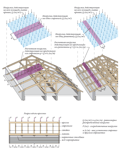
truss system
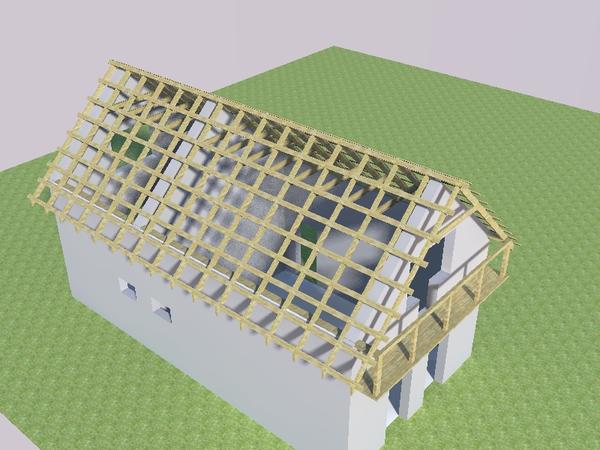
Elements truss system rest on the supporting structure of the wall, which creates a load on the foundation of the building structure.The choice of truss system is determined by the type of roof.
As a rule, the design of the rafters is not visible against the general background of the roofing device. However, its importance should not be denied, since it is a high-quality frame that gives stability and strength to the entire roof structure. Moreover, the quality of the truss system should remain unchanged, regardless of the type of roofing (tiles on the roof or galvanized iron, euro slate or rolled materials).
In any case, the calculation of the dimensions of materials for the device of the truss system must ensure the mechanical strength of the structure.
The calculation criteria should include:
- Material type;
- Roof structure;
- The feasibility and economy of construction.
Calculation of the truss system produced at the design stage of the roof.
It includes the following items:
- Calculation of the section of bars for rafters;
- Calculation of the pitch of the rafters
- span calculation;
- Development of a rafter laying system (rafter truss and structure);
- Analysis of the strength of the supporting structures of the structure;
- Calculation of the use of additional elements (if necessary - braces and puffs).
Attention. During the construction of a typical project, you can use the standard calculations specified in building codes.
For individual construction, this issue must be approached especially, taking into account the conditions of construction and the configuration of the structure.
Calculation of the section of truss elements
The selection of the section of the rafters depends on the following indicators:
- roof plans;
- Natural loads characteristic of the climatic region;
- rafter lengths;
- The angle of inclination of the slope and, accordingly, the rafter legs.
The correct calculation of the geometric parameters of the rafters will ensure the strength of the structure.
Wooden beams or metal elements can be used as truss elements. Recently, many builders began to combine these elements into a single structure.
It is worth noting that the metal surface is characterized by the appearance of condensate, which, dripping onto wooden elements, leads to their decay. In the calculations of truss elements, we will focus on the case of using only wooden elements in the structure.
Here are some calculations for the section of the bar for rafters:
- With a rafter length of 4 m and an angle of inclination of 30 degrees, a bar with a section of 50x140 mm is used;
- Accordingly, 4.3 m - 35 degrees - 50x150 mm;
- 4.6 m - 40 degrees - 50x160 mm;
- 4.95 m - 45 degrees - 50x170 mm;
- 3.9 m - 25 degrees - 50x140 mm.
This section is suitable for projects with the placement of rafters at a distance of 1.6 m from each other.
With an increase in the spacing of the rafters, the thickness indicator increases. The construction market for standard projects produces roofing materials having a length of 1 m. Therefore, a pitch with the same size is most often used in the design of the truss system.
Note that reducing the step size from 1.6 m to 1 m does not lead to a decrease in the cross section of the beam for rafters. So, provided that the beams are placed 1 m apart, it is necessary to use the section calculation that we gave above.
Step between rafters
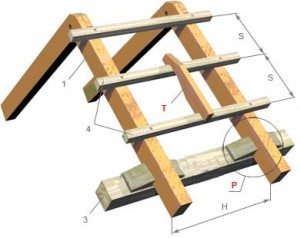
The basis of the rafter structure is a triangle, consisting of the upper belt of the truss - the rafter legs, and the lower belt - the puff. The upper ends of the rafter legs are connected to the run on the ridge. Fastening of the lower ends is carried out on the walls of the house from the outside.
The ability to withstand the load of the rafters is due to the step from the placement.
The step of the rafter legs depends on many indicators:
- Roof forms (hip, gable or single slope);
- slope slope;
- Beam section parameters (width and thickness);
- Structures of the truss system (layered or hanging);
- Roofing weights (agree that slate, roll materials, profiled sheets have different weights);
- Sections of the lathing material (50x50 mm, 20x100 mm and others);
- Types of crates (solid or with a step).
Of course, if all indicators are taken into account, then the calculation will give a guaranteed result in the direction of creating a reliable roof under high loads, which are determined by the technical characteristics of the roofing material and the requirements of building codes.
To establish the step width, the standard and design load is used. Usually, the normative is determined by the norms of SNIP, and the calculation is carried out by a constructive method. Depending on the size of the roof structure and roofing.
A common option is to use a bar with a section of 5x15 cm and a laying step of 80 to 180 cm. With an increase in the slope of the slope, the rafter step expands.
For example:
- With a ramp slope of 20 degrees, the step is 80 cm;
- Angle of 75 degrees - the step is 130 cm.
When calculating the step width, the length of the truss elements is taken into account. When increasing the size of the rafters, you cannot increase the distance between them.
Let's give an example of calculating the step (cm) taking into account the length of the rafters (m) and the cross section of the beam (mm):
- 60 - 3.0 - 40x150;
- 60 - 4.0 - 50x150;
- 60 - 6.0 - 50x200;
- 110 - 3.0 - 75x125;
- 110 - 4.0 - 75x175;
- 110 - 5.0 - 75x200;
- 175 - 3.0 - 75x150;
- 175 - 4.0 - 75x200;
- 175 - 6.0 - 100x250.
Advice.If during operation you will need to move along the roof, it is recommended to set a step between the rafters of 85 cm with a slope of 45 degrees.
Purpose of calculations
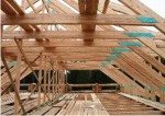
As we have already said, the need for calculations is due to obtaining a good result - the installation of a reliable and durable roof. The development of calculations is aimed at identifying the limit state of structural elements, that is, resistance to deflection and destruction.
The calculation indicators given above were carried out taking into account the slope of the slope, snow and wind loads, the weight of the roof, the height of the building, which determines the resistance of the elements to destruction.
The resistance to deflection is determined by the normative loads, which differ for each region. The value of standard loads is contained in SNIP for the design and calculation of the truss system.
Roof system plan
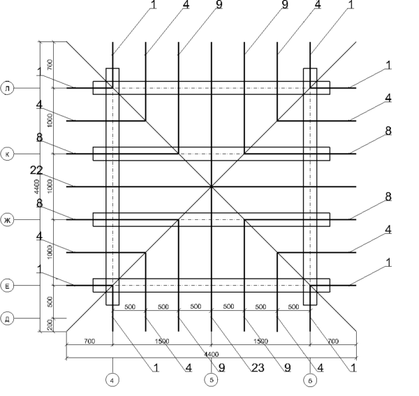
After carrying out all the calculations and preparing the material, you can proceed to the construction of the truss structure. For proper installation, the rafters are laid out.
The layout plan is:
- The position of the truss elements (legs) is determined.
- Marking is applied to the rafter pairs.
- The position of the pairs relative to the wall structure is determined.
The plan is developed based on the type of truss support. For light roofs, a construction of rafter legs and a lower puff can be used. Heavy-weight roofing requires the inclusion of additional supporting elements in the truss structure.
Here is an example of some types of truss structures:
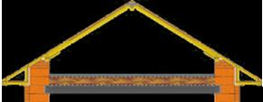
- Layered (the Mauerlat acts as a support for the rafter legs - the support beam; the distance between the supports is 6 m);
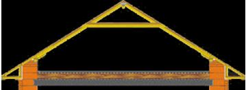
- Layered with crossbar (in this design, a puff is mounted between the rafters, which ensures resistance to deflection; the distance of the supports for the rafter legs is 8 m);
- Sloped with medium support (in addition to the support beam and rafter legs, a rack is installed under the ridge, struts are attached to it and the rafters; this allows you to increase the strength and rigidity of the structure, as well as the step between the supports up to 12 m).
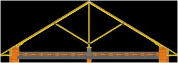
Attention. A pair of struts is always fixed in the rack to evenly distribute the load of materials on the truss system.
The use of constructive measures of calculation and laying of rafters leads to the protection of the roof from the effects of loads of roofing materials, wind, snow cover. Competent calculation eliminates the need for major repairs before the expiration of the warranty period for the materials used and installation work.
Did the article help you?
