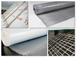
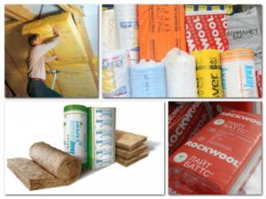
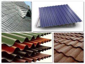
| Illustrations | Description of stages |
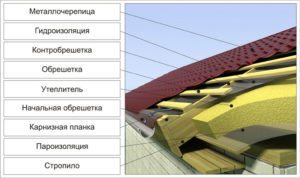
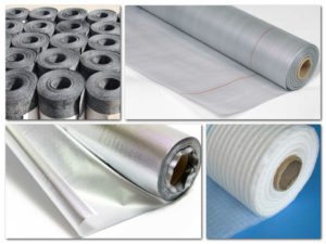
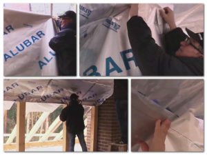 | Installing a vapor barrier membrane. The vapor barrier layer is rolled out from the inside of the room perpendicular to the direction of the rafter legs. If a membrane with a metallized layer is used, then this layer is lined inside the room. The vapor barrier layer is shot with a stapler with your own hands to the rafters and glued with metallized tape. |
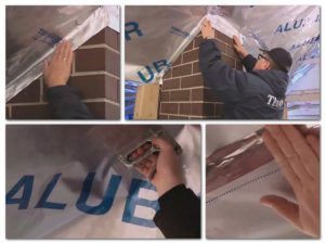 | Joints and junctions of vapor barrier. At the junctions of adjacent strips, the vapor barrier is laid with an overlap of 15 cm. Moreover, the strip located below should find its edge on the strip located above. The overlap and adjoining of the vapor barrier to the gables is glued with a wide metallized adhesive tape. |
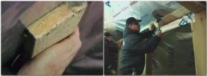 | Vapor barrier lining from the attic. In order for the sealant to be firmly fixed and not to push through the vapor barrier, from the side of the attic, we fill a continuous crate onto the rafters. The boards are fastened transversely to the rafters in increments of 30 cm. |
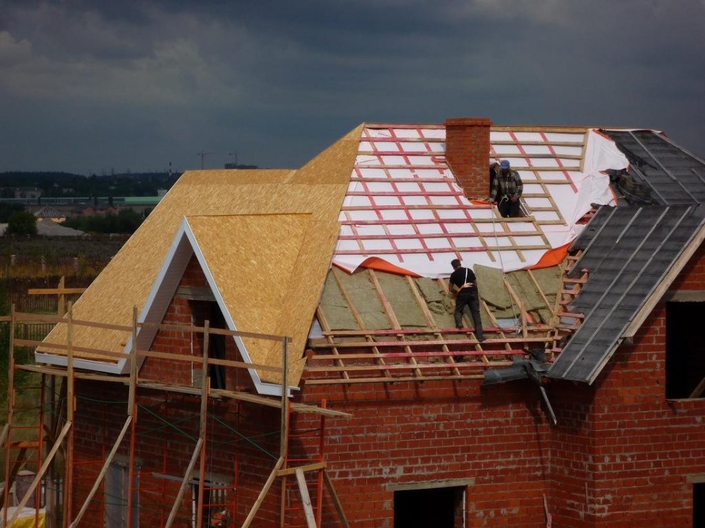
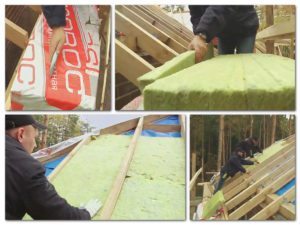 | Insulation installation. We unpack the package with mineral wool boards. We lay the heat-insulating material in the gap between the rafters in two layers with an offset relative to each other. That is, the top layer should cover the joints between the plates in the bottom layer and prevent cold bridges. |
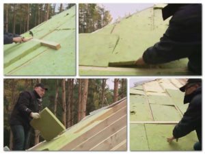 | Installing the counter beam. Bars with a section of 50-50 mm are nailed across the rafters. The beam is attached in increments of 60 cm. A mineral wool slab 50 mm thick is laid between the nailed beams. This slab eventually bridges the joints on the previous layers of insulation. |
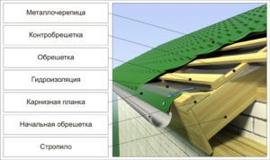
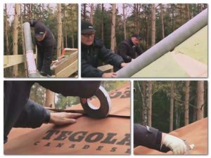 | Laying a vapor-diffusion (waterproofing) membrane. Waterproofing is lined with stripes in the direction from the roof overhang to the ridge, that is, from the bottom up. The waterproofing strips are laid on the previous strip with an overlap of 15 cm. The overlap line is glued with high-quality double-sided tape, and then fastened with a stapler along the counter beam. |
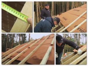 | Making a ventilation gap. On top of the membrane, in the direction of the rafters, a bar of 50-50 mm is laid out. A step of 30 cm is maintained between adjacent bars. The bars are nailed to the counter-beam. Through each meter of timber, as shown in the photo, a passage is made so that adjacent ventilation ducts are combined and better ventilated. |
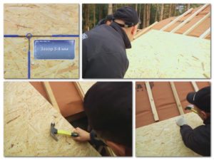 | Rigid base for roofing. Approximate particle boards (OSB) with a thickness of at least 1 cm are laid out on top of the bar that forms the ventilation gap. A compensation gap of 3-4 mm wide is left between adjacent fragments of plates. |
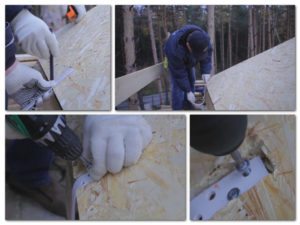 | Installation of gutter holders. After the roofing pie is covered with a rigid base, brackets for the gutter are applied to the edge of the overhang. The junction of the bracket to the overhang is outlined with a pencil, and then, along the intended perimeter, a chisel is selected with a chisel to the thickness of the bracket. Brackets under the steel gutter are installed at intervals of 60 cm. |
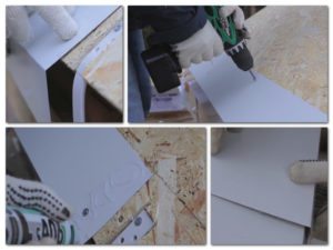 | Installing a drip. A dropper is an additional roofing element that is installed on the roof structure along the edge of the overhang. Droppers are fastened with self-tapping screws for metal with a flat head.Silicone sealant is applied at the place where the two drip strips meet and an overlap of 10 cm is made. Installation of the dripper is carried out after the drain brackets are installed.
|
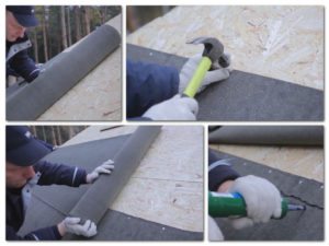 | Installation of additional waterproofing. On top of the OSB boards, we lay rolled waterproofing. The first strip is placed with an overlap of 3-5 cm on the edge of the dropper. To do this, double-sided tape is glued on top of the dropper. The other edge of the waterproofing is fixed with roofing nails in increments of 30 cm. The second strip is laid with an overlap of 10 cm on the first strip. A bituminous sealant is applied along the joint line. |
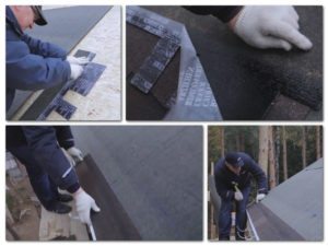 | Laying the first row of shingles. We cut off the petals from the strip of tiles and remove the protective film. We apply the prepared strip over the drip, so that the strip protrudes 1 cm forward beyond the waterproofing. Bending the upper edge of the roofing, apply bituminous mastic. We nail the strip along the upper edge with roofing nails in increments of 20 cm. |
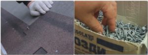 | Laying the remaining tiles. The next fragments of the soft roof are laid with an overlap on the previous strip. That is, the petals of the second strip should reach the bottom edge of the first strip. We fasten soft tiles along the upper edge and on the sides with special roofing nails no longer than 2.5 cm and with a flat head diameter of 9 mm. |
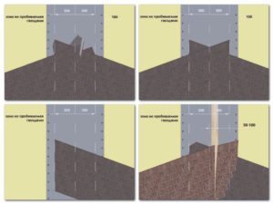 | Laying tiles in the valley. If the slopes adjacent to the valley have an equal slope, the “pigtail” laying method is used. Tiles alternately from two sides start up on the valley. If the roofing cake is made with a different slope of the slopes, the scoring method is used. The instruction is simple: - First, the tiles are laid on a slope with a small slope with a spade on the opposite slope, where the excess is trimmed;
- From the opposite slope, tiles are started up and cut over the previously laid coating.
|
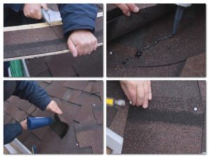 | Laying the ridge element. We cut off the petals from the strip of tiles, and cut the remaining strip into equal square pieces. We stuff these blanks onto the roofing cake along the ridge line for two nails. As a result, each installed fragment should hang over the previously installed fragment. Before laying a piece of tile, we apply bituminous mastic and heat the tile with a building hair dryer
. |
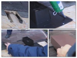 | Ventilation installation. A hole is cut in the OSB for the base of the aerator. An anti-mosquito net is attached over the hole. We apply a layer of bituminous mastic along the perimeter of the grid. We put an aerator on the mastic and fasten it to the sole with nails. We apply mastic along the perimeter of the sole of the aerator, on which we put the tiles. |
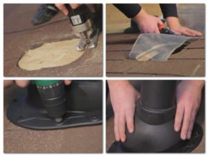 | Installation of feed-through elements. The sole of a passage element, for example, a ventilation pipe, is applied to the roof surface and outlined with a marker. - According to the markup, a hole is cut in the tiles and in the OSB. An anti-mosquito net is attached over the hole;
- Bituminous mastic is applied to the mounting side of the sole of the passage element;
- The sole of the passage element is applied to the perimeter of the hole in the roof and screwed with self-tapping screws.
|
